Showing posts with label Repairs and Maintenance. Show all posts

Saturday, October 26, 2024

The Goofy X-Spread Rig on The F-24 MKI

10-26-2024, rev. 11-6-202, rev. 11-27-202, rev. 12-7-2024

The failure of an F-24 mast at the lower diamond wire junction this week (not my boat) started me thinking about the odd rig on this boat. It was not used on any other F-boat, and in fact, no other boat that I can find. Supposedly Gino Morreli designed the rig, but he's a smart guy and he never used this design on any other boat. I'm think it's far more likely this was a John Walton (son of Walmart founder Sam Walton) design choice, one of many that Ian did not approve of. Oops.


 The failure point was just above the lower (forward) diamond wires. Note also that it was sideways (as typical), not in the direction of the forward wires, suggesting to me that they are not helpful.

Mono-hulls are typically rigged with spreaders and shrouds anchored to the deck. This provides side support with no added compression load. The proportional stretch of the uppers and lowers insures that the mast remains accurately in column, even as it is slightly deflected to the side under wind loads. Masts, when they buckle are failing in compression. Occasionally a jumper diamond is provided on the front to control the bend of a very slender mast, though larger mast sections and those stabilized with pre-bend typically do not require this extra support.


One the left (F-24) rig there are two sets of diamond wires on each side. The drawing omits the outer set on the left and the inner set on the right for clarity. Those are not loaded when the mast is pressed to the side and forward reaching.

 Re. Center of effort.  According to calculations based on ABS (American Bureau of Shipping) documents, the force on a sail is primarily concentrated on the head, clew, and tack. A quick look at the reinforcements and the arraignment of fibers in load path sails makes this obvious. Consider how the luff is relaxed when the sail is backwinded. In fact, about 65% of the sail force above the boom is concentrated at the head, with the balance spread along the luff tape. The load is NOT uniformly distributed along the mast, as commonsense might first suggest.


The weird F-24 X-spreaders. The forward spreaders hold the shorter wires. The aft spreaders are about the typical rake angle and provide the pre-bend. 


 F-24 manual image.


Multihull masts are often rigged with big rotating masts for several reasons. A big main is advantageous, as it provides accurate heel control through twist and easing the mainsheet. They can tolerate a heavier mast (rotating masts must be heavier because the staying is less efficient) because they heel less and as a result, the mast is not outboard, contributing to heel. They have a wide shroud base, reducing the need for spreaders to create angle. Often multihulls cannot sustain high mast base compression loads because there either is no center hull, or in the case of trimarans, because it is lightly built, without the need for structure to support a keel.  For the same reasons, rotating masts are nearly non-existent on monohulls. Because there can be no fixed spreaders to carry side loads, rotating masts use diamond wires, and it works out well that they rotate with the mast, supporting the weak side of a thin, aerodynamic wind section. Forward support isn't needed, because the mast is wide in that direction. The diamond spreaders are angles aft to help create some pre-bend, which helps with mast stability (resists inversion and pumping) and with draft control (you can de-power by de-rotating the mast which pulls cloth out of the sail, reducing draft).

 The combination of diamond wires, aft-swept spreaders, and aft-angled cap shrouds also helps eliminate the need for a fixed backstay, something that is problematic with a high roach mainsail, the other half of the quick-heel-control formula. It's hard to maintain enough forestay tension without a backstay, and savy multihull sailors quickly learn to compensate with a tight mainsheet.

But the F-24 MKI mast does not rotate, so why the diamond wires, instead of fixed shrouds? It's easier to step the mast when trailering, since no tensioning is required. The center hull is relatively narrow and very light, with no good place to anchor the shrouds. There is also the need for aft-raked cap shrouds to replace the backstay. Of course, many cruising cats have either conventional shrouds or diamond wire stays with aft raked cap shrouds and no second set of diamonds.


There are several problems with the willy-nilly addition of stays without working through the design. When a mast fails, it fails in compression. Like buckling a drinking straw, the tensioned side does not tear, it is always the compressed inner side that buckles inwards. Every additional wire and its associated pretension adds compression, so unless it provides needed support, it actually weakens the mast. The more wires, the more compression. Calculations of buckling strength for this mast sections give a compression working load of 6,500 pounds. Rough calculations based on wind pressure and heeling force (the boat was reefed and very close reaching) and bending moment at the failure point  show that the mast failed under a compression load of about 12,000 pounds (if distributed--this reflects the probable stress on the side that failed). This is well over the safe working load of the section, but less than the expected failure strength.

If we total up the compression loads from the shrouds, diamond wires and other rigging ...

  • Forestay. 2200 pounds
  • Shrouds (only one is under much tension sailing under full load). 1200 pounds
  • Mainsheet. 300 pounds
  • Halyard, jib. 300 pounds. Note, jib halyard tension does not change forestay tension + halyard tensions at the mast, only between the mast and the anchor point at the furler. The total is fixed by shroud and mainsheet tension contributions.
  • Halyard, main. 500 pounds
  • Cunningham. Does not count, since it just offsets friction in the mast groove, from head to foot.
  • Forward diamonds. 1000 pounds total (but not included at failure point)
  • Aft diamonds. 2400 pounds total

... and adjusting for angles (only part of the tension is directed in-column) we get about 6,500 pounds total. That does not allow a lot for bending moment. Curiously, 36% of this is from the diamond wires and 10% from the forward diamonds, which we don't need; there is very little forward load on the mast, and the center of the force is near the head of the sail (forces perpendicular to the luff tape are very low, except near the head and tack--not the wrinkles, the luffing when backwinded, and the lack of significant reinforcement on the slug grommets).

The rigging guide gives 500 pounds max for the forward diamonds and 1000 pounds max for the aft diamonds. But what if they really don't need pretension for stretch, since the mast is not bending? Then the pretension for the aft shrouds needs to be just enough to establish the prebend (0.8% of length), and forward diamonds just enough to keep them from going slack, since we probably do not need them at all. But I'm disinclined to remove them entirely, and going slack might allow them to jump out of their fittings. 

10-29-2024. I checked the tensions on my F-24 MKI.

Wire                  Observed (pounds)              Maxium Spec (pounds)            Re-set to (pounds)

Shrouds             800  (may reach spec in strong winds)  1500                       (adjusted each sail)

Forestay            (same as shrouds by geometry, except as increased by mainsheet tension)

Aft Diamond     1400 (over spec, below)      1000                                           800

Fore Diamond    800  (over spec below)       500                                             350  ____________

Total Diamonds  4400                                    3000                                           2300

 This represents a (4400-2300)/6500=32% reduction in mast compression, which translates dirrectly into a 32% increase in strength. 

Data source: from the 1992 F-24 manual


 Worse, exactly where the reefed main applies it's greatest force (65% of the drive above the boom), just above the forward diamond wire anchors, the lee diamond wire is pulling down and to leeward. And that is where the mast buckled to leeward with a reefed main. The smoking gun. Removing or slacking the forward diamonds also reduces this stress. 

What if the mast raising stays were snugged and perhaps reinforced in the deck (Lower shroud)? This is a conventional rigging solutions? This stabilizes the lower mast with less compression in the critical area. It would also help to move the anchor point slightly aft and outboard, while staying inside the jib track.

Takeaways? The forward diamond wires increase compression and pull in the wrong direction without providing any useful improvement in mast stability. Best would be a re-designed mast with only one set of aft-swept spreaders. The less drastic solution is to reduce the tension on the forward diamonds; I judged 300 pounds to be sufficient preload and sailing observations confirmed they do not go fully slack.The aft diamond wires should be just tight enough to create 2.5 inches of pre-bend (as specified by Ian Farier)  and no more. These serve a purpose, but extra tension does not help. 800 pounds appears to be sufficient, and I may reduce this, based on further sailing observations in strong conditions. 

Will I reinforce the deck and improve the lower shroud? Undecided. No. The wires are too small to bother.

Time will tell, but I'm comfortable with my calculations. The mast should now be 30-35% stronger, no small improvement.

---

rev. 12-7-2024


A few more ideas. I could support the center by running a second set of shrouds to the same anchor point. In this way, they would move together.  In addition, they would be tensioned along with the cap shrouds. My gut is that fixing the diamond wires makes this unnecessary. I have to address the diamonds anyway.


Monday, July 22, 2024

Rudder Shape. Building a Better Rudder

Elliptical was all the rage for racers in the 80s to 90s. Now we're seeing some extreme shapes with tails.  Is it fashion of function? Maybe both.

First, defining the project for my boat and the problem:
  • I don't want to replace the rudder with a transom hung upgrade. I like the swing down cassette for aesthetic reasons (I'm weird), the transom would require modifications to mount one, it would interfere with the boarding ladder, and there is nothing mechanically wrong with the rudder or cassette.
  • I have added an anti-ventilation fence to help with high speed ventilation. It helped, but there is still not enough control in some sea states. This was designed and speced by the designer of the boat, Ian Farrier.
  • Although the rudder cassette is OK, I am mindful of not adding much more bending moment. The bearing carrier is DWV PVC, is sunburned, and can't take much more. I have replace the bearings. I also navigate some very shallow waters. I do not want to increase the draft. [The rudder in the F-24 MK1 is mounted in a cassette at the transom that is rotated up with a rope to lift it out of the water. When lowered into possition it functions like a spade rudder.]
  • The rudder feel is very light. In fact, the rudder is so over balanced I can often let go for a minute upwind in good conditions. She just goes straight. I'm calculating ~ 22% balance, and I think something in the high teens would make more sense.
The core of the problem is that the F-24s have low volume amas that are very prone to driving down off the wind. If there is a steep quartering sea, they like to bury, followed by the stern lifting and the boat immediately rounding up. When the bow buries it becomes like a new centerboard forward, moving the COE and making it impossible to turn and bear away. Monohulls and catamarans do this, but it is many times worse on a trimaran, in part because of the fine amas and in part because of smallish rudders. 90% of the solution will always be balancing the sail plan, and bearing away preemptively and surfing away (really fun, by the way), just before the bow buries, but a little more control would be nice.  I really don't care about racing speed or class rules, but I do like a boat that is fun to drive.

As I said, adding a fence helped. Now I am considering changing the rudder plan form slightly. The Spitfire elliptical profile has proven strengths, but within the constraints (length and ventilation near the waterline) there is probably room for an upgrade. Ian speced out the anti-ventilation fence I have and he changed rudder designs for other models over the years.

The Dragonfly rudder seems pretty extreme, but they're smart guys. Jeffa uses a more squared off profile. There are many examples and I don't really want to go too far down the design rabbit hole.
 
 
 2024 Dragonfly 28. a pretty extreme tail. This would drastically affect balance and would affect the shaft placement. I'm not interested in creating a heavy helm.
 
 Jeffa Rudders cruising designs.
 
My current idea. I have not decided how much area to add. Call it option A and option B.
 
This also seems more in line with F-24 Mk II (top) and F-28R (bottom) rudders, which are known to be more effective and less prone to ventilation and loss of control.


What about just adding a little area down low and aft? This should decrease the balance to about 17-18%, where it should be, increase the turning force about 5-8% in calm conditions, and perhaps 10-15% in tough conditions when the upper portion of the blade is ventilating.The area is added to the deepest part, where the water should remain air-free.

An apparently successful and slightly more radical F-24 MK1 rudder modification.


I'm pretty good with fiberglass, and I've built paddles and dinghy rudders before. The fairing will take some figuring, templates, and some time, but it really is a small area. Seems like a fun project. I like tinkering.

Thoughts?


Sewn Splices


 Traditional splicing of rope eyes is the gold standard, but there are times when it is not practical:

  • The line is old and stiff.
  • It is a line, like climbing rope, that cannot be spliced by conventional methods because the cover is too tight.
  • The position of the splice must be precise.

 Enter the sewn splice. This is often seen on sails, and can be made strong for larger eyes by using more stitching. The strength is about the thread strength x number of passes, and add a 50% safety factor. Also protect from chafe with a webbing or other covering.

I've been using sewn splices for 30 years and I have not experienced a failure yet, though I do cover those that are exposed to chafe.

I made this video for Good Old Boat Magazine as a companion for an article on the topic some years ago.


Thursday, July 18, 2024

F-Boat Hinges and Stainless Bolt Failure

 Edit 7-19-2024. Edit 7-21-2024: I originally posted the images just to share them with a metallurgist. They deserve some explanation.

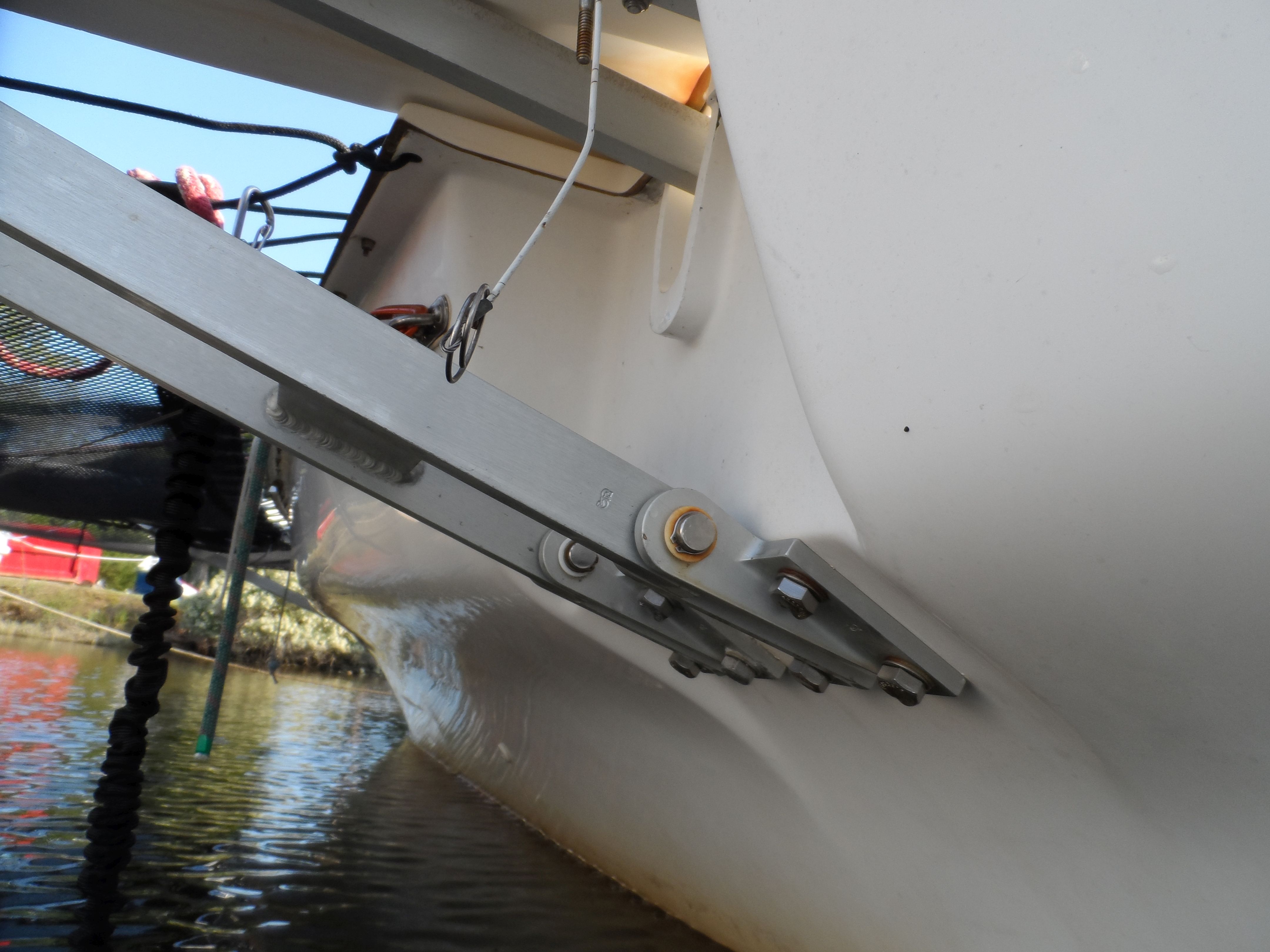
The bolts are not from my boat. They are from an F-9A, a home-built version of the Corsair F-31. The hinge design is similar. I know of three F-9As that have suffered from this problem and no other F-boats. I don't know why this is the case, but I have educated suspicions.

When the bolts fail, even if over 50% of them are bad and the others compromised, the structure does not fail. It is very conservatively engineered. Although stress certainly plays a part, I suspect it is only the pre-load (installation torque) and not service loads. As long as the service load does not exceed the installation pre-tension, the bolt does not "feel" the change in load. The fitting experiences changes in stress, but the stress under the bolt head does not change. This is one of the primary reasons for pre-tension (in addition to preventing loosening, but they are related). As long as the pretension does not exceed the working load limit (WLL) there is no fatigue, not change in stretch, no movement, no failed seals, and no loosening.

These bolts are loaded in nearly pure shear, so the failure point, if related to sheer, should be at the flange/hull interface or even farther in, not at the head. The fore-aft loads from the amas are carried by diagonal cables. The view is from the aft hinge forward. The forward hinge is just visible in the distance.

So why are they failing at this location, and why only (I think) on the F-9A?

---

 I asked the owner of one of the boats for more detail. This is what I go. He obviously put some thought into it.

All the ones (bolts, washers and nuts) I removed were 304 series (A2), it is isolated from the aluminium bracket with a glass reinforced acetal washer.  This sort of crevice corrosion is quite common in saline environments where a water film can get trapped and not flushed.  It is a significant area of interest in offshore oil and gas where the use of duplex steels (which have austenitic and ferritic phases) is common which are designed to be more resistant to this type of corrosion.  One of this issues is there is no great way to tell if a fastener has crevice corrosion.  PERN number, which is a ratio of  chromium, molybdenum, nickel, and nitrogen content is often used to compare the resistance of steel to this type of corrosion.  PERN is approx18 for A2 (304), 24 for A4 (316) and mid 30s for duplex.  I notice the farrier sailing manual suggests no maintenance is required except flushing the bolts with fresh water if feasible.

---

[Corsair F-24 lower folding strut. A smaller boat, but a similar design.]


Sometimes the head of the bolts come off due to crevice corrosion under the heads. Only under the heads. The bolts are epoxied in, creating a good seal, but who knows.  Another possible difference with this F-9A vs. the production Corsairs is the used of glass-filled acetal washers in place of 304 stainless washers. Was the glass possibly abrasive? There should have been no movement. Some other chemistry, possibly related to why bolts more commonly break inside the laminate?

These boats, unlike the production version, used carbon in the beams. Some builders used it extensively. Carbon is quite noble and could be a factor.

This is more like what I would expect, but it is not what we see on F-boats.

This can also affect hinge pins (F-28R).


The F-28R and the F-9A contains some amount of carbon, but whether it was used in the affect area is not known (these boats are on their 2nd owners). Certainly not near the failed pin.


More F-9A parts


---

I'm puzzled as to why these problems do not seem common in the Corsair production versions. I'm glad, mind you, just puzzled. As more information becomes available, I will revise this post.


Thursday, May 23, 2024

Mixers

The problem with most paint mixers is that they are a pain to clean. Use them a few times, and they are so clogged up with a thick layer of paint that they lose their hydrodynamic shape.  The one of the left was used maybe twice, the one right many dozens of times. The difference is that I can wipe it right off. The flat plate design can loosen the thickest solids without clogging.

 
You really can't buy the sort on the right. Most of mine were lab mixers. I have dozen and will leave them to my children. A few, for special sizes, I made by welding a rectangle to a length of rod. If you can't weld, I'm sure the plate could be soldered to the side of a flattened rod.


Saturday, April 6, 2024

A Slow Leak

11-12-2019 (see 2024 update below)

 What do you do when the boat develops a 1-2 gallon per day leak, where you can't get to it, and it isn't time to haul for a year? The F-24 is a trimaran and cannot sink due to main hull flooding. Add that there is nothing other than fiberglass below the probably flooding limit (no wood and no wiring to speak of). Most people would just let the sump pump handle it. Except there is not sump pump.

As an added complication, the sump is only 3/4-inch deep before it reaches the level of the floor. On the other hand, the floor is a bath tub-like hull liner that unless holed, can easily manage 6 inches of flooding.

First, you plug any holes you can reach with underwater cure epoxy. No kidding, the stuff really does work, and I'll be doing a review for Practical Sailor soon. 

I used JB Waterweld. Scrub the area clean, but it does not need to be dry. Wet you hands. Sounds funny, but do this or it will stick to you more than the boat, which doesn't work. Cut off as much as you need and mix by kneading. rolling between your palms and folding can also work. Then press it into the hole with your fingers, with special attention to rubbing down the edges. This takes a few minutes of steady, gentle rubbing. You have to move the water out of the bond area. But within a few minutes it will be sticking well everywhere you rubbed. Keep rubbing it down for a few more minutes, until you can feel it begin to firm, which takes about 10 minutes. It will be hard within an hour.

It is not as strong as conventional epoxy, but it is strong enough for the purpose and may be permanent. 

Unlike conventional epoxies, it does not generate a run-away thermal reaction and over heat. Underwater there is cooling, of course, but even in the air it will not seriously exothermic. In fact, I know often use Splash Zone for certain filling applications, for example around through bolts, because it tolerates moisture in the laminate, because it does not exotherm, and because the cure is also relativly quick.


Then you add a sump pump. I went with something smaller than the standard Rule pumps, because I wanted to such lower and because rate was not that important to me. This one will remove about 2 gpm through a 1/2-inch ID hose, which is what I had in mind. I mounted it to an aluminum bridge, which I bonded to the hull with ... underwater epoxy.

I played with micro switches that would activate the pump at lower water levels than the standard 2-inch on, 3/4-inch off settings, but found them unreliable. So I went with a rule switch which I mounted with ... underwater epoxy.


I then added a sub-panel. I had some other lighting circuits that needed straightened out too.  A piece of Coosa Board, a terminal block, and a bunch of crimps did the job. The water hose was relocated later. The hose ties into the sink drain with a through-tee, so no added through hulls. This also gave me a chance to clean up the hose runs so that there are no low spots that can freeze; all of the water drains either to the sump or overboard.

The timer is the neat twist. I wanted the pump to have a chance to keep up with small leaks, before the water reached 2 inches, so I set the timer to trigger the pump for 1 minute every 24 hours, but I can adjust that if the level rises.

 And so far (4 weeks) this seems to be working nicely. I did jump last time I was sailing and the sump pump came on. Surely, I have a leak! But it was simply the scheduled 1-minute run time.

-----

Coosa Board Bluewater 26 is a fiber reinforced (several layers of woven cloth, just below the top and bottom surfaces) polyurethane foam that is lighter than plywood and will not rot, but not quite as strong. It sort of holds screws, but not like wood. It is MUCH stronger than non-reinforced foam, nearly as strong as plywood. It is normally laminated with fiberglass for structural use, but not always. It's really neat for fabricating small parts that need some strength and which you will glass over. Little flanges. Shelves. Braces.

4-2-2024 

Five years later and still holding. In fact, I did a bunch of tests for PS. The winners were Splash Zone from Pettit (strongest) and JB Waterweld (fastest plugging). The Waterweld is still holding, in part because we could never find the source of the leak from the outside. Amazing stuff, I will always keep a package handy in the future.

The pump and timer are doing fine. With only minute of run time per day there is little wear. It will move more water, however, when I clean the bilge, for example.


Monday, December 25, 2023

Wiring Color Codes

I used to think there was something like a standard color code, but then I learned that trailers were different. Then I bought stuff from Amazon (no instructions) and learned that the UK, Europe (IEC) and China also have unique codes, and they are different.

 
So now I can figure out my Chinese stuff. My boat, on the other hand, has parts from Asia, Europe, and the US, and there is no color code I can derive. So I stick with black and red and label the ends where they are not obvious. 

(BTW, the reason ABYC does not use Black for the 12 V negative is to avoid confusion with the 120 V hot. My boat doesn't have a 120 V system, so I'm not worried. The IEC also specifies a different color for the high voltage neutral (blue).


Monday, November 27, 2023

New Stuff I'm Testing for Practical Sailor

Rev. 7-24-2024

 Of course, the you'll need to subscribe to get the full story. I hope you will. PS is one of my favorite research tools. Every subscription comes with access to the full archives, which is a whole lot.


Seam Sealing Tape

The leading cause of death of rain gear is loose seam tape. 25 years ago I bought a 3-layer Goretex jacket and pants with bad tape and good fabric. I glued the tape down with contact cement and it stayed through 20 years of occasional use. But it was a laborious process. More recently I bought a second hand spray skirt (it came with a sea kayak) with bad seam.

I tried gluing the tape back down again. It worked, but was laborious. I tried Seamgrip from the outside; it worked, but doesn't look great. It tried several highly regarded SA tapes, even using tape primer. A waste of time. But iron-on seam tapes work great. Use a name brand (Bainbridge).

The shoulder/back seam is iron-on, the armpit and side is glued.


Penetrating Epoxy

 I never really looked into it, because West Systems says it's useless. I'm only part way into this, and I feel like West Systems is about 70% right.

  • Penetrating epoxies are 3-5 times weaker than conventional Epoxies. Weaker than Gorilla Glue and about the same as varnish.
  • Penetrating epoxies are really slow to cure, like days. And they must be fully cured before over coating (they are not compatible green even within the same brand).
  • Does not help the bond. Would you bond to varnish? I didn't think so.
  • Not at all water tolerant, perhaps less than other epoxies. So much for rotten cores, which are surely damp.
  • Adding acetone actually reduces effective penetration. When the acetone dries it pulls some of the epoxy back to the surface with it. The epoxy does not penetrate with the acetone. The acetone does not improve water tolerance. Don't add acetone ... ever.

 On the other hand, there many be some uses.

  • Varnish undercoat. But I have no evidence that it sticks better than or is more durable then thinned varnish.
  • Sealing questionable edges after a hatch replacement. Bear in mind that it will delay the project another several days.
  • Use slow cure epoxy instead. It will penetrate nearly as well, since it has time, and will be full strength, and will be compatible green within the same system.

But I'll know more in a few months. I'm going to be leaving samples to weather.

As you can see, it has not really penetrated good wood, since it is still on the surface. 

 
Coatings for Tramps and Amsteel
 
The tramps on my F-24 and PDQ came with PVC coatings to reduce UV damage and chafe. The coating has worn off, so I recoated with the factory stuff (Sunrise Yacht Products). It seems to be a durable, flexible, high adhesion coating, so I will be exploring other uses.
 
Amsteel comes with a Samthane coating to reduce chafe and snagging. Samson does not sell the coating, but Yale Cordage does. Dilute about 3-5:1 until watery and work it into the rope. It won't stay on the outside--it will rub off--but that does NOT mean that it isn't protecting, by reducing UV penetration deep into the rope and reducing snagging of individual yarns, which is an important failure mode for Amsteel.


Can you tell which is new Amsteel and which is DIY coated Chinese Dyneema?
 
A little messy, but it's water-borne, so not bad. Wipe off the excess.
 
 18 months later the coatings are rubbing off a bit, but...
  • The part that counts is really inside.
  • Not anymore than the factory coatings did.


  •  


Tuesday, February 28, 2023

National Elelctrical Code Shore Power Plugs

 I've been hearing a lot of fanfare about Smart Plugs, much of it from smart people I respect. But strngely, they are still not listed  in the NEC, by NEMA, or recommended by ABYC. Since only greater than 30A is acceptable for shore power, these are the only plugs you can use:

ABYC allows a few more, through you will never see the 4-pin and the 20A cannot be used for shore power.

 
Less common are pin and sleeve connectors, only seen used for higher loads.


One reason, of course, is compatibility. A mix at marinas would be a further mess and require more (sometimes dodgy) adapters.


Monday, February 20, 2023

Velcro For Winch Handles

 rev. 7-24-2024

 I tested this for a month. It was OK but just didn't suit my style.

I ended up making a custom holder from PVC pipe that ...

  • Is cut on an angle so the handle always lays against the bulkhead
  • Fits snugly in an unused corner.
  • Has no bottom so it never gets dirt in it.
  • Attached with VHB tape. VERY strong, no new holes. Do wipe the surfaces with alcohol first.
 But Velcro did work. The handle never fell off.

 I've never been a fan of the PVC pockets. Cloth ones only last so long. PVC pipe can be pretty good, but it works best in a corner (see above).

What about Velcro? I've been seeing this on more and more sport boats, and I can see some advantages:

  • A fraction faster.
  • No holes to drill.
  • Might lose more handles ... or fewer if the pockets aren't being used.
  • Can store grip-down, making it less snag prone.
  • Velcro will only be good for about 2 years in the sun.
  • The hooks can grab some fabrics, but located low this is unlikely.
  • Fits all sizes.
  • Could be horizontal.
  • Grip won't mar the gel coat. 
  • Not in the way when not in use. Put a pad by every winch ... but then where is the handle?

On the other hand

  • Grabbing the handle might be more awkward. 
  • It will get dirty and green.
  • Can't be used for anything else.

You could do both. 1-2 conventional pockets, and then pads near every winch.  I may try that.

The hook part goes on the boat and the loops on the handle. I guess it could go either way, but hooks on the handle would feel strange and not give a good grip.


Thursday, February 16, 2023

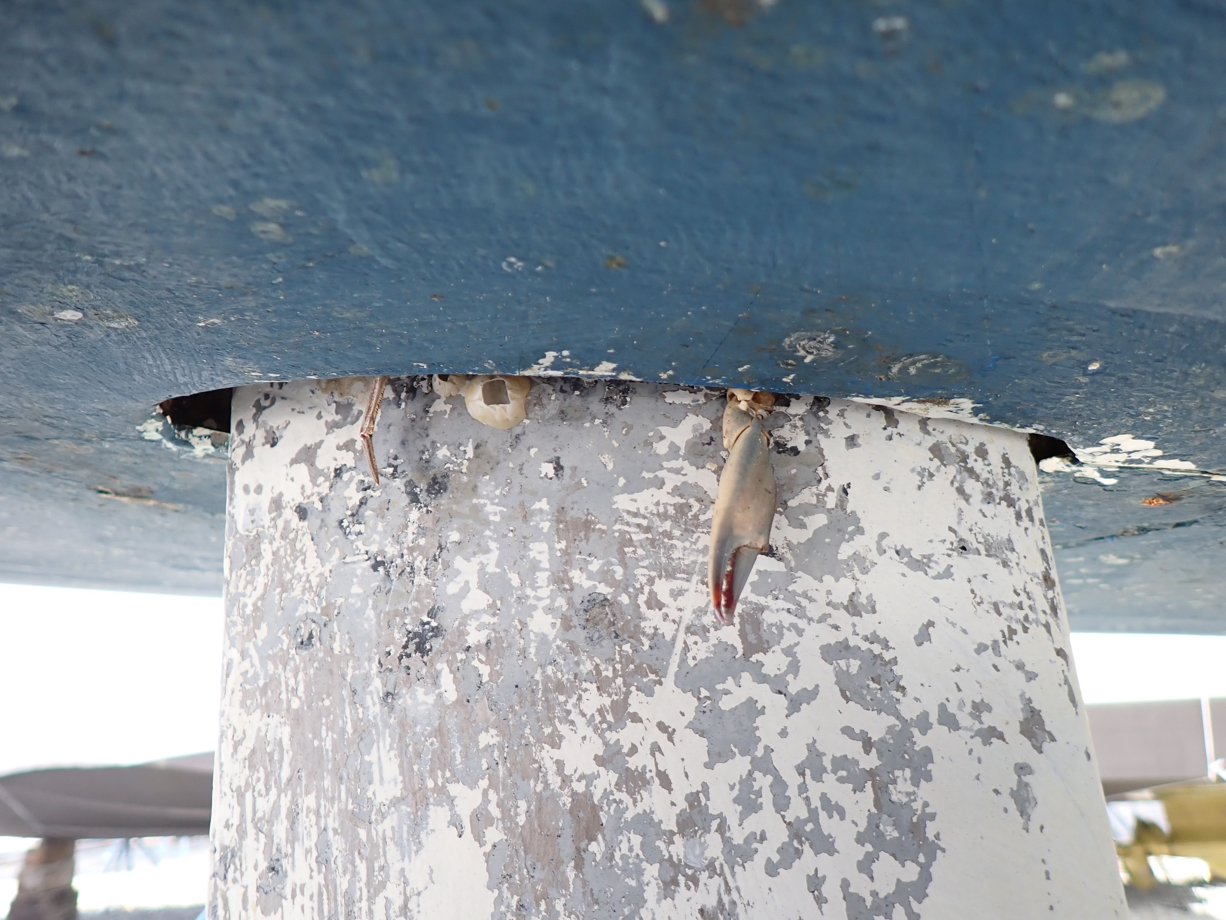
 I imagine he took up residence when he was small, and then one day learned he was stuck. [sail drive]


I'm currently 22 months into a 24+ month evaluation of bottom paints in the Chesapeake Bay for Practical Sailor Magazine. More than 20 samples and 6 different paints on my boat. In spite of copper leach rate restrictions, and to the credit of the paint manufactures and the EPA, we seem to have a crop of paints that are quite effective and kinder to the environment.

I have conventional foul weather gear, but my winter sailing gear is based on waterproof socks in deck shoes, snow board pants, and a windbreaker over fleece. When it gets colder, add a balaclava and a warmer parka. I love the new Gill Helmsman gloves (the only insulated gloves I can really sail and work winches with), and ski goggles come out when it gets close to freezing.


Friday, November 11, 2022

No Wet Sanding

Rev. 7-24-2024

 Given the rules, my aversion to scraping, and the health risks associated with every stripper I've see (either methylene chloride, NMP, or high pH) I'm not a fan to start with.

 So the project before my next bottom job will be to pick out a new vacuum sander. I have a DeWalt 1/4-sheet sander that I use with a HEPA vacuum and a Dust Deputy. The vacuum part works find, and the sander was inexpensive and has been very durable. I don't feel cheated, not at all. But removal rates are slow and it is not random orbit (leaves swirls).

The other motivation is that I did some paint testing for Practical Sailor, including 6 types on my boat. All of the copper paints are doing well, but two of the non-copper paints really suck, so there will be some serious sanding involved. 

What are the criteria? 

  • Speed of removal.
  • Appearance and swirls. Within the random orbit class, this is more related to the grit and use than the sander.
  • Vibration. Includes ergonomic shape and padding.
  • Dust collection.
  • Weight. Overhead, it adds up.
  • Price. But the older I get that matters less, as I have learned the value or quality tools.
  • Durability (all of the candidate brands should outlive most DIYs
  • Usability. Includes nimbleness and one-hand operation.
  • Size. Still undecided. If the hull is curved, larger does not put that much more sanding surface on the hull.

 So who's in the running?

  • DeWalt. The RO 5-inch is faster than what I have and only $65.
  • Bosch. The dual mode GET75-6 is expensive but leading the wish list. Supposed to be very fast, but it's near $300. But time saved from sanding bottom paint counts triple on your life score.
  • Porter Cable. They have a 6-inch RO for $160 that is well regarded.
  • Fein. They also make an anti-fouling sanding "fleece" that may fit others.
  • Festool. Had to put it on the list. About double the Bosch for the same size.

In the end I went for the ...

  • Makita BO5041. $129.00
Not the cheapest, but it got great revues for speed of removal and ergonomics from boat building schools.  So far (two years) I'm a fan. A bottom job and many, many home projects. It's not as fast as the dual mode sanders, but it is lighter and is what I needed. For a big bottom job, the Bosch is the boss.


Tuesday, October 18, 2022

Deale Anti-Fouling Paint Test Panels at the One-Year Mark

 A total of 26 paints on 30-some panels, including 5 paints on my boat (it's sort of multi-colored).

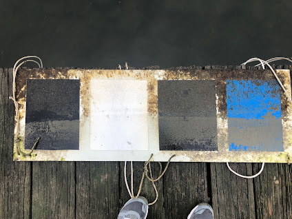
These panels have been hanging alongside the dock for a year in Deale, MD. The water is brackish, only about 30% sea water concentration, but it is a high fouling area none the less. The far right (upper) panel is a control, not coated. It will be a 2-year test, so these paints are only half way there. Needless to say, some are failing, but the cold will knock the soft growth off and we'll have to see how they look in the spring and next fall.

If I give away the results my publisher (Practical Sailor), who paid for all of the work, panels, and paints, will kill me.They should publish the full report soon.

Nearly all of the paints are compliant with the new California low-leach-rate requirements, which we believe will be adopted in Washington and perhaps nationally before long, since the EPA seems to be onboard with this approach. Since the paint companies have been involved and can make some darn good paints that comply (and are no more expensive, adjusted for inflation), it seems the whole copper paint kerfuffle has come to a win-win resolution. 

I'll be picking my next bottom paint from these panels!


Thursday, February 3, 2022

Testing Paint

 Late Summer I hung 7 test panels with 20 paints from a dock in the Mid-Chesapeake Bay (Deale, MD) as part of a Practical Sailor project. Prior projects have all been seawater. I also applied 50 of these paints to my Corsair F-24. Today I pulled them out for a quick look see. No cleaning, just a check-up.

We don't get much growth in the cold season.You can see it in the non-painted frames. Some are doing amazingly well (the white is actually still that white), and some not very different from untreated areas.

All of the paints are either copper-free or formulated to the new EPA/CA/WA copper leach rate, which most of the good multi-season paints already met (or the copper would not have lasted 3 years--kinda of obvious in retrospect.


They'll be hanging there for 3 years, with us checking on them about twice per year. We'll rotate positions. In the summer they will hang from floats to better control the depth (ice is a problem in the winter).


Friday, July 9, 2021

The Desiccating Head

rev. 7-24-2024, 10-5-2025

Three years later I'm still thrilled with this for a daysailor and even for weekend cruising on a small boat. Basically, anytime the alternative is a port-a-john.  

  • Less odor. Practically none if properly managed.
  • Lighter by 2-3 times.
  • Easier to service. No lugging the whole thing off the boat. Just bag it and toss.
  • No winterizing.
 I built mine largely from fiberglass, because I had the tanks handy for free, but plywood could be very good if well caulked and then well-painted. It really does not get messy in there.


 My Stiletto 27 had a portable toilet that stunk. Use the right chemical and it stinks less. Every time it is used a laborious haul/dump/clean process is triggered.

My PDQ 32/34 had a nice holding tank system that I had engineered to perfection. No odor, nearly like home. But it required space and weighed a good bit. Perfect for the PDQ, but totally unsuitable for the F-24.

We really only day sail the F-24 trimaran, and the head is only for emergencies. It didn't get used for years at a time, so we switched to WAG bags. Never used them.

 I'd been poo-hooing composting toilets for years. I'd experienced some nasty ones in cabins and some friends had a bad experience with a Natures Head. In fact, both failures probably included elements of design and operator error.

I was asked to investigate the topic, and so I did. There was a long-winded article in Practical Sailor last month, covering both toilet design, absorbents, and anti-odor additives for the urine tank.

 There are two keys to function:

  • Separate the urine from the solids. First, the smell is greatly reduced, and second, the solids side it much drier, preventing it from getting wet and aerobic.
  • Dry the solids. Like any animal dropping, once it is dry on the outside, there is little odor. That is the function of the absorbent; to speed drying, filter the air, and cover. It is NOT to cause composting. This is a desiccating toilet. 

There simply is not room on a boat for true composting toilet. The process tanks months, requires temperature and moisture control, and continuous mixing and ventilation.  Since you cannot effectively compost, then stop pretending and dry the waste instead. You can then take it home and compost it if you like, or double bag it and dispose of it like litter box scoopings. Your choice. The urine is odor-free once treated (see below) and can be disposed of easily.

I built a test version from a storage tub, a bucket and scraps to test the absorbents and additives. It was a crude thing, but in fact I used it in the basement bathroom for two months, during which it proved to be amazingly odor-free and easily to deal with. I was stunned. It was time to eat a large helping of crow. But I was happy to eat the crow, because the result was a truly user friendly head solution for my F-24.


A perfect fit. Note the shedded aspen pet bedding, TP, and spray bottle of citric acid to the right. Necessary supplies. 


The final version was based on molded parts from Separatte, a fiberglass tank I modified to fit the available space, an under seat baffle I cut from fiberglass, and yes, a bucket and jug. The top hinges up for service, which is a simple matter of lifting out a bag and replacing it; a clean, contact-free process. The absorbent of choice, at any price (I tested many), is millwork sawdust and shavings I get for free (aspen bet bedding is also very good). The urine treatment is citric acid, though vinegar and Nilodor are also very good.

I no longer see any point in conventional portable toilets, at all. A desiccating toilet is better in every way. Regrettably, you must either pay a king's ransom or build your own.
 
The separator kit from Amazon.

 
The general arrangement. The body of the head is a modified fiberglass battery box, so it is watertight and easy to clean (hose it out). The hinged lid is heavy plywood, well painted. The bucket was cut down to fit. The urine jug was something I hunted for a perfect fit. I added a butyl rubber grommet made from a truck inner tube.
 
Proper operation includes covering the solids with a thin layer of wood shavings (aspen worked best, after testing many materials in a prototype). The primary function of the cover is to wick moisture away from the surface.
 
Odor can be even further reduced, to zero, by hanging a small mesh (I used tramp fabric) sachet of swimming pool bleach inside the box. Moisture triggers a very, very slow release of chlorine, which oxidizes any odor. It lasts about a year. (Black bag on the back left side, hanging from a hook.)
 
I tested it in a spare bathroom in my house for a month before taking it to the boat. Honest, no odor if operated correctly. The spray bottle is ~ 1% citric acid to lightly rinse the urine separator; kills the smell and prevents the scale build-up common in urinals. 
These are the internals of the C-Head, now out of business (owner passed away). 


Sunday, February 21, 2021

Drogue Chainplate Design

rev. 7-25-2024

 Don Jordan, the father of the series drogues, suggested a chainplate of conservative dimensions, but did not detail the design. He wanted to keep it simple so that people would use them. Most commonly, these plates are installed horizontally, because that looks right. But what if the pull is not horizontal?

 The angle are exaggerated to make a point. Tank or model testing would could refine this. But I'm pretty sure that not all of the strike sure horizontal and thus the first few bolts are carrying most of the load.

In my limited experience, and based on what I think is common sense, the strongest pulls are from a downwards angle. From basic engineering statics, the largest bending forces are near the transom end, and the largest shear loads on the bolts will be when the load is off-axis. That suggests either more or larger bolts near the transom, but more will better distribute the shear stress load to the laminate.

Hardly a detailed analysis, just thinking. In practice, it would be simpler just to build it oversize, though internal reinforcement of the laminate might be avoided by this sort of design.